
Bottom line: A reliable phone case mold program starts with device data and a written DFM review, then proves fit, surface quality, and repeatability through documented samples. Buyers should compare the complete tooling process, not only a quoted mold price: steel choice, cooling, gate design, texture control, revision terms, and the inspection plan determine whether a private mold becomes a dependable OEM asset.
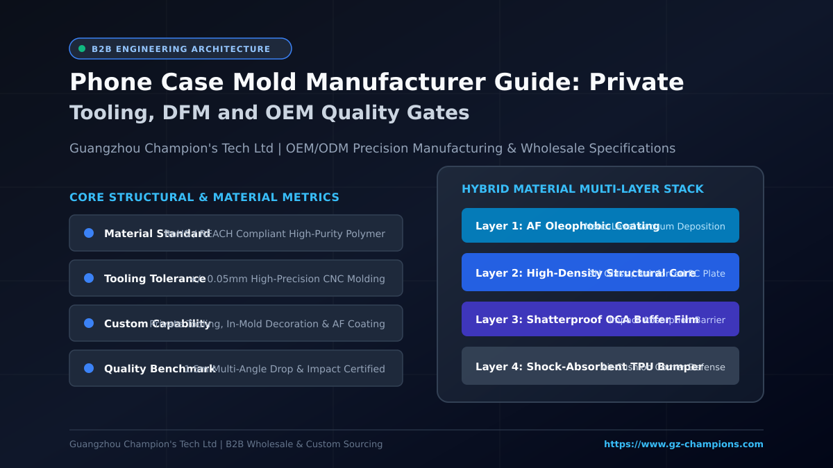
This technical guide is written for distributors, brand owners, accessory procurement managers, and hardware engineering teams evaluating private injection tooling for protective cases. Whether sourcing thermoplastic polyurethane (TPU), polycarbonate (PC), liquid silicone rubber (LSR), two-shot hybrid structures, MagSafe magnetic arrays, in-mold decoration (IMD), or precision custom enclosures, mold development represents the single largest upfront capital commitment and risk factor in your product rollout. The external consumer pages retrieved during market discovery discuss DIY epoxy resin pouring and desktop craft molds; those materials are noted purely for background context and share no engineering overlap with industrial steel tooling. Every commercial specification, tolerance limit, and production schedule must be validated directly against manufacturer DFM approvals.
1. Define the mold technical package before requesting an RFQ
Approving a tooling quote based solely on an aesthetic rendering or rough concept sketch is the primary cause of tooling delays, parting line flash, and costly steel rework. Phone case geometry requires micron-level accuracy around camera bezels, tactile switch buttons, charging ports, and speaker cutouts. Any minute deviation in the underlying CAD shell will amplify once steel is cut and polymers shrink in the press.
A rigorous specification package sent to an injection mold maker should contain:
- Target phone model and official CAD revision: Explicitly note release dates and hardware revision numbers, as flagship smartphone brands frequently revise camera bump heights, microphone hole locations, or chassis radii between design leaks and final commercial releases.
- Controlled 3D and 2D engineering drawings: STEP or IGES files accompanied by fully toleranced 2D PDFs highlighting critical-to-quality (CTQ) datums and baseline tolerances (typically ±0.05 mm for perimeter snap-fit interfaces).
- Material selection and compound grade: Specify polymer type, hardness (e.g., Shore 85A to 95A for TPU, optical-grade PC), flame retardance (UL94), and color codes (Pantone/RAL) rather than generic names.
- Surface finish and texture requirements: Define SPI polishing standards (SPI A2/A3 for high gloss, SPI B1/B2 for semi-gloss) or standard mold textures (VDI 3400 or Mold-Tech standards) to determine necessary draft angles.
- Annual volume forecasts and cavitation target: Single-cavity prototype tools versus 1+1 or 2+2 family production molds demand fundamentally different cooling and runner layouts.
2. Match mold construction to phone case architecture
Different phone case product structures dictate distinct tooling complexities, parting line splits, and slide mechanisms. Understanding how your product architecture drives mold design ensures technical feasibility before committing capital.
| Architecture | Typical tooling focus | Buyer acceptance question |
|---|---|---|
| TPU or PC single shot | Gate vestige, cooling balance, draft and ejection | Is the gate hidden and is the parting line outside the hand-contact zone? |
| TPU + PC hybrid | Insert location, overmold adhesion, shrinkage compensation | How will the supplier control insert movement and flash at the interface? |
| Liquid silicone (LSR) | Cold runner, venting, cavity sealing and flash control | What sample plan proves the seal edge remains clean after repeated cycles? |
| IMD or printed film | Film registration, draw depth, wrinkle prevention and trim | What datum controls artwork alignment from cavity to finished part? |
| MagSafe case | Magnet pocket, steel shielding and charging clearance | Are magnet grade, location and pull-force targets written into the drawing? |
3. Tooling steel selection, runner systems, and gate dynamics
The choice of core and cavity steel directly governs tool life, polishability, corrosion resistance against outgassing resins, and overall dimensional stability across hundreds of thousands of shots. Aluminum or soft pre-hardened steels (like P20) may suit short prototype runs, but production-grade smartphone case molds demand premium European or Japanese tooling steels.
| Steel grade | Typical hardness | Primary advantages | Best suited application |
|---|---|---|---|
| S136 / S136H | 48–52 HRC (hardened) | Superior corrosion resistance, mirror polishability (SPI A1), minimal wear | High-clarity optical PC, premium clear TPU, liquid silicone rubber tools |
| NAK80 | 38–42 HRC (pre-hardened) | Uniform hardness without post-heat treatment, excellent EDM machinability | Textured hybrid frames, intricate button inserts, precision slide cores |
| 718H / 2738 | 32–36 HRC (pre-hardened) | Cost-effective core toughness, good thermal conductivity, stable dimensions | Mold base plates, support blocks, budget multi-cavity protective cases |
| H13 | 46–50 HRC (hardened) | High thermal fatigue resistance, high strength at elevated temperatures | Heavy-duty structural case inserts, glass-filled composite reinforcement |
Gate selection is equally critical to the cosmetic presentation of consumer phone accessories. Submarine (tunnel) gates or pin-point hot runner valve gates allow automatic degating while positioning the vestige inside the hidden interior rim or beneath decorative badges, eliminating manual gate trimming blemishes along the outer gripping edge.
4. DFM engineering checkpoints and validation gates
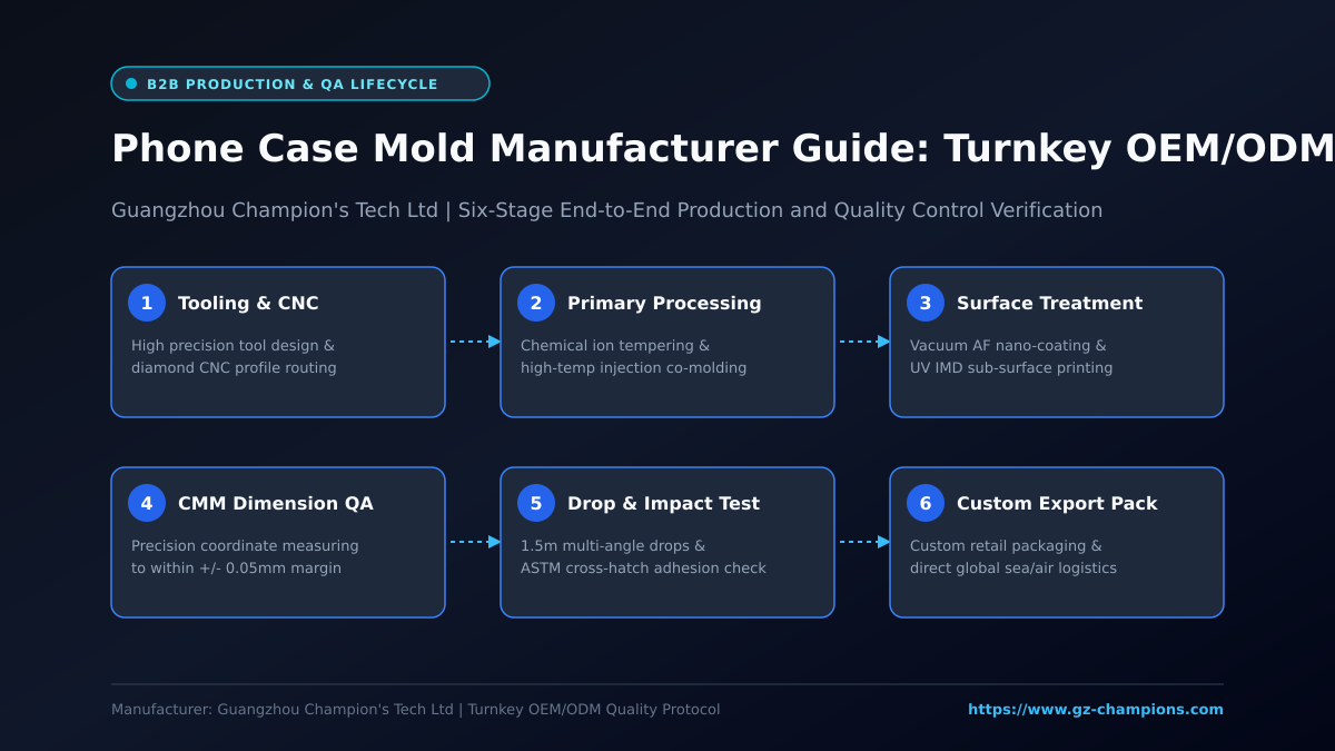
A capable injection mold manufacturer conducts comprehensive Design for Manufacturability (DFM) analyses prior to machining steel. The buyer should insist on a formal engineering sign-off package containing the following sequential gates:
Gate A: Moldflow simulation and thermal analysis
The engineering team must simulate melt front progression, volumetric shrinkage, sink mark probability, and weld line positioning. In thin-wall case geometries (1.2 mm to 1.8 mm), improper gate placement forces weld lines directly across high-stress camera bridges or thin button ligaments, creating latent structural weakness. Cooling channels must follow part contours (baffled or conformal cooling) to prevent non-uniform shrinkage that causes corner curling and bow warp.
Gate B: First trial (T1) and comprehensive CMM inspection
The T1 trial exposes how polymer behavior interacts with actual tool thermal balances. When samples emerge from the mold, inspectors evaluate them for flash, short shots, jetting marks, and ejector pin push marks. Dimensional verification should be performed using Coordinate Measuring Machines (CMM) and optical video measuring systems (VMM) measuring key coordinates against 3D CAD datums. For multi-cavity tools, each cavity must be measured and cataloged individually to detect cavitation imbalances.
Gate C: Engineering Validation Test (EVT) assembly fit
Even a dimensionally in-spec case can fail functional validation if device tactile feedback or drop retention is compromised. During EVT, trial cases are fitted to genuine target smartphones and precision metal test fixtures. Teams verify that click feel on power and volume buttons requires appropriate tactile actuation force (typically 200–350 gf), wireless charging efficiency meets QI/MagSafe thermal boundaries, and edge lips elevate screen glass at least 0.8–1.2 mm above flat surfaces.
5. Quality checklist for private phone case tooling programs
- CAD Revision Lock: Ensure the tooling purchase order locks the exact 3D revision hash, preventing silent file overwrites during revisions.
- Parting Line and Gate Sign-off: Confirm parting lines sit along natural parting chamfers and that ejector pin locations avoid visible external surfaces.
- Cavity Identification: Check that every mold cavity features engraved cavity numbering (e.g., C1, C2) for traceability during high-speed production runs.
- Datum Scheme Consistency: Align measurement datums across the mold maker, case molder, and receiving inspection teams to prevent gauge discrepancies.
- Resin Shrinkage Assumptions: Formally document specific shrinkage percentages calculated into steel dimensions (TPU: 1.2%–1.8%; PC: 0.5%–0.7%; LSR: 2.5%–3.5%).
- Physical Device Gap Inspection: Measure physical clearance gaps around camera lenses, USB-C/Lightning cutouts, and speaker grills using feeler gauges and optical comparators.
- Surface Texture and Visual Defect Limits: Establish signed visual defect boundary boards defining acceptable versus rejectable thresholds for micro-scratches, sink, and knit lines.
- Magnetic Force & Alignment Verification: For MagSafe cases, verify neodymium magnet ring positioning, flux orientation, and minimum pull force retention against steel test plates.
- Tool Life and Maintenance Warranty: Ensure tooling agreements guarantee shot count life (e.g., 300,000 to 500,000 shots for hardened steel), routine maintenance intervals, and spare insert availability.
- Commercial and Milestone Transparency: Verify that DFM sign-off, T1 sample approval, and final golden sample sign-off serve as clear commercial milestones before mass production release.
6. Key supplier qualification criteria for OEM/ODM buyers
When selecting a manufacturing partner in China or Southeast Asia for proprietary phone case tooling, technical expertise must be paired with clear intellectual property safeguards. Buyers should inquire whether tooling is engineered and built in an in-house toolroom or subcontracted to third-party machine shops. In-house toolrooms dramatically accelerate engineering change orders (ECO) when phone brands introduce unexpected last-minute dimensional tweaks.
Furthermore, clarify tool ownership and storage protocols. Reputable contract manufacturers treat custom private molds as client property, maintaining exclusive storage, insurance, and regular preventive maintenance logs. Separating quotes into clear line items—tool design, base machining, EDM/CNC finishing, sampling runs, and unit piece price—protects buyers from hidden cost markups and enables fair benchmark comparisons.
7. Build your custom tooling RFQ with CHAMPIONS
Creating a differentiated smartphone case line requires transitioning from generic open-market molds to precision private tooling designed specifically for your brand aesthetics, impact protection standards, and accessory ecosystems. Guangzhou Champion’s Tech Ltd (CHAMPIONS) provides comprehensive OEM/ODM engineering support, covering DFM evaluation, precision private mold fabrication, multi-material injection molding, liquid silicone tooling, MagSafe magnetic integration, and advanced decorative finishing.
To ensure your development program moves smoothly from engineering CAD to commercial inventory, review our technical capabilities across our OEM/ODM services, explore tailored manufacturing options in custom phone cases, and consult detailed material engineering articles in our Knowledge Center.
Ready to initiate your custom mold program? Contact our technical engineering team directly to submit your 3D models and specification sheet for a comprehensive DFM assessment and formal quotation: Send an OEM/ODM tooling inquiry.
Ready to Build Your Custom Phone Case Line?
Send your product type, target model, material, packaging request and estimated quantity. The CHAMPIONS team will review the project details and reply with the next steps.